Reverse design of the air intake cavity wall of aircraft engine
Lufthansa's largest repair base in Germany adheres to the rigorous work principle. It needs to perform three-dimensional reverse on the air intake cavity wall of the aircraft engine, and obtain high-precision three-dimensional data for mold opening processing, which reduces the difficulty for post-repair work.
Practical problems
1. The air volume of the intake hole of the aircraft engine is large. The traditional measurement method is too low in efficiency and low in precision. It is difficult to reverse design and modeling in the later stage. Waste too much human and material resources.
2. The curvature of the outer surface of the air intake cavity of the aircraft engine is difficult to measure by manual. The customer is required to obtain complete and accurate data in a short period of time, so that the follow-up work can be carried out quickly to ensure high quality service.
CO3D solutions
The customer hopes to obtain complete and accurate three-dimensional data of the air intake cavity of the aircraft engine in a short period of time. The three-dimensional shape is based on the customer's difficulties and proposes a solution: using the camera-type 3D scanner HL-3DS+ fast and accurate The three-dimensional data of the air intake cavity wall of the engine is obtained, and the scanned 3D data is imported into the software to fit the SLT triangle mesh surface, and the three-dimensional design software is imported for reverse design. The product structure design and improvement improved the efficiency, the follow-up work was carried out quickly, and the service project was completed within the specified time.

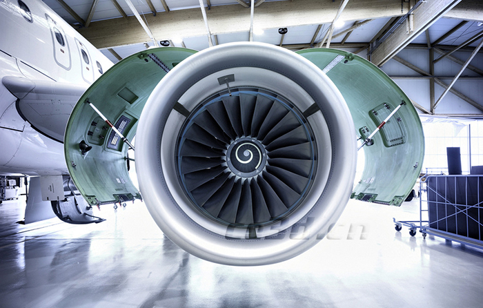
Aircraft engine intake hole cavity wall renderings

Aircraft engine intake cavity wall scanning site

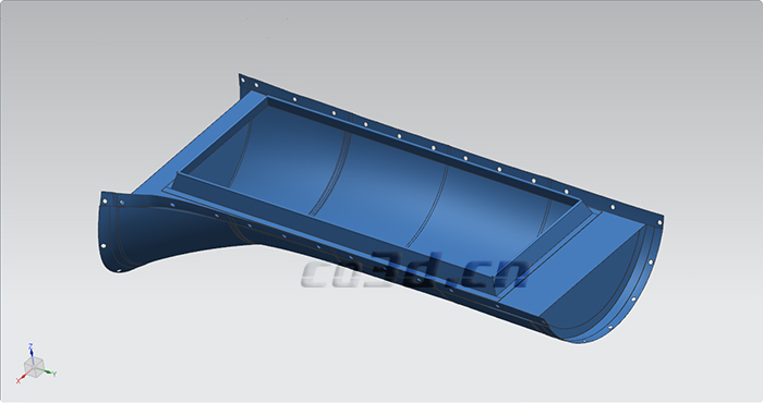
Aircraft engine intake cavity wall STL data diagram

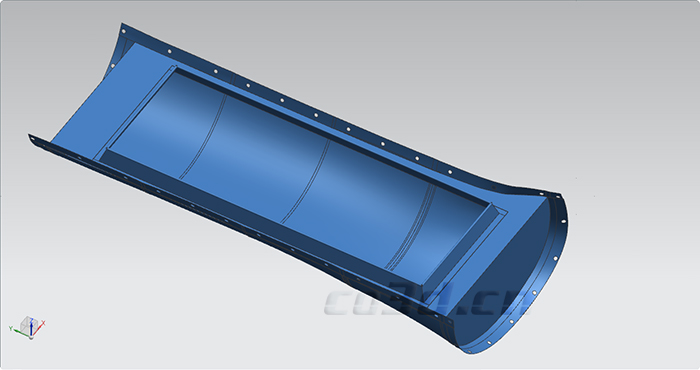
Aircraft engine intake cavity wall STL data diagram

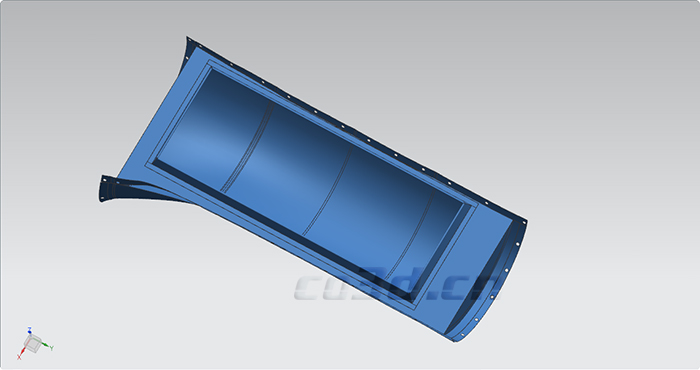
Aircraft engine intake cavity wall STL data diagram