Three dimensional inspection of engine blades
The blade is a key part of aero-engine, and its manufacturing volume accounts for about one-third of the total machine manufacturing volume. Aero-engine blades are thin-walled and easily deformed parts. How to control its deformation and process it efficiently and with high quality is one of the important research topics in the blade manufacturing industry.
Practical problems
1. Use a hand-held 3D scanner to inspect the engine blades, compare the acquired 3D data with the standard parts, the accuracy is 0.02mm, and process the unqualified parts.
2. Using traditional measurement methods (checking jig, jig, three-coordinate, etc.), the acquired data is incomplete, and the curved surface cannot be measured, resulting in an incomplete amount of acquired data, and subsequent work plans cannot be carried out.

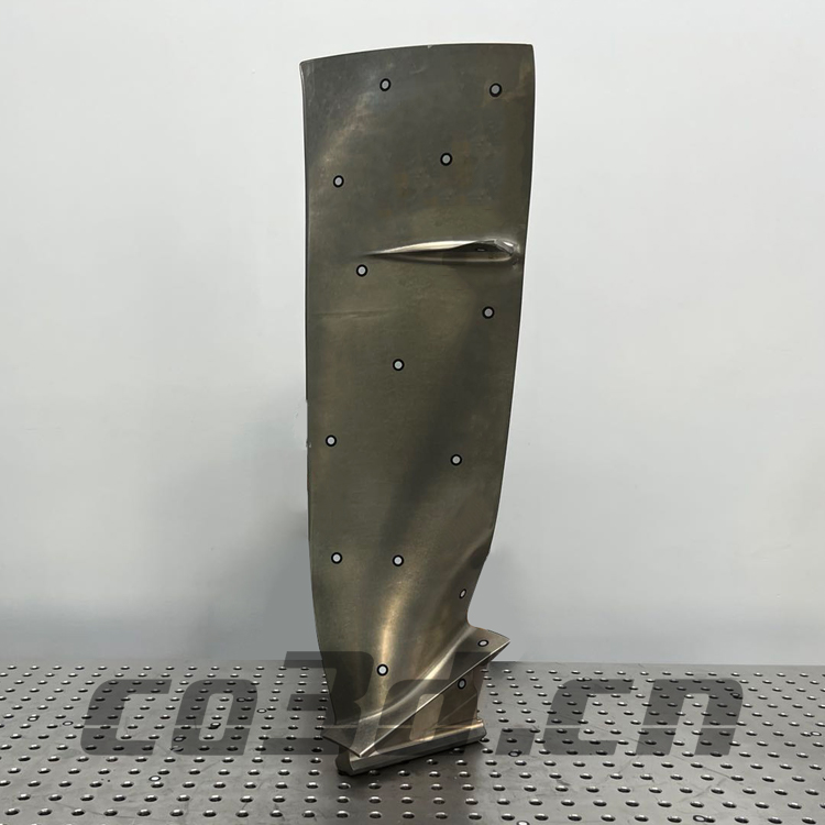
Physical map of engine blade
Solutions
Equipment used: Handheld 3D scanner HOLON B71
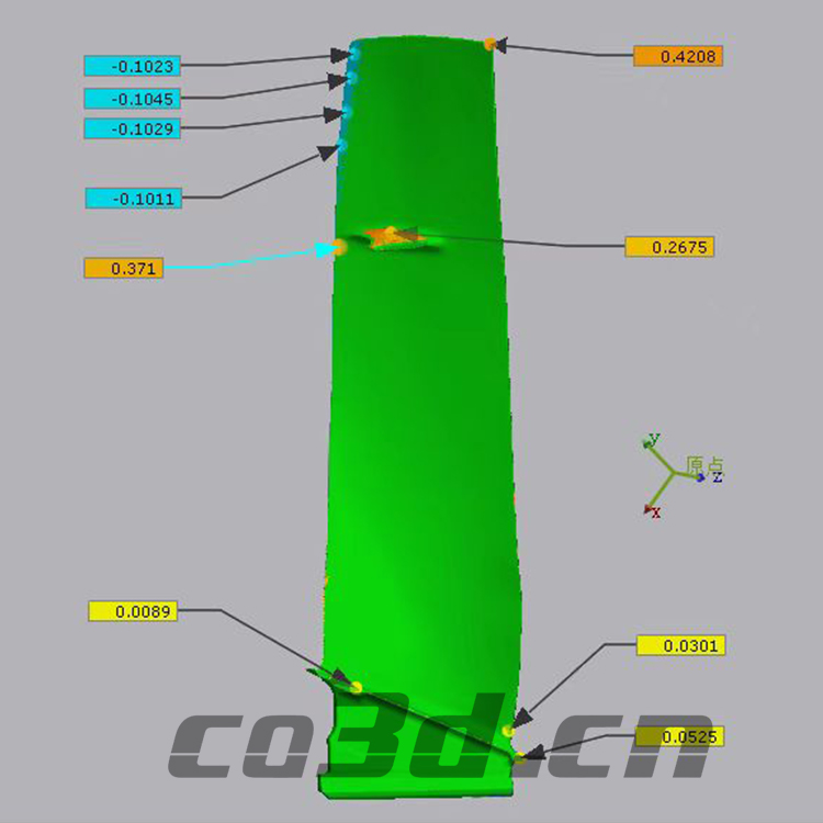
All blue laser scanning is adopted, the scanning speed is 1,350,000 measurements per second, dual industrial cameras, automatic marking point splicing technology and self-developed scanning software have high scanning accuracy and work efficiency. By comparing with the original data, the error of actual processing is detected.

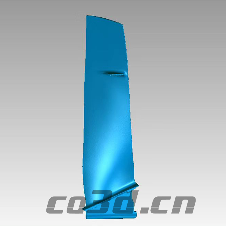
Engine blade STL data map

Engine blade comparison test chart